Thursday, September 30, 2010

Motor Lab

Day 1: Today, we had our motor lab project. The goal was to build an electric motor that could spin a minimum of 3 complete rotations. My partner Steven and I began our project by first getting a piece of wood which we made sure was not compressed. Then, we used nails and a hammer to puncture 4 nails in the wood. The 4 nails were assembled in a square shape, with a nail at each corner. The square's dimension's were approximately 3cm long by 5 cm wide. While I hammered the four nails into the wood, Steven used sandpaper to sand the strips of aluminum, which would eventually become our brushes. Our next step was to assemble the cork, the axel, and the commutator pins. We did this by penetrating the middle of the cork with the axel (a thin wooden stick). Then, on the sides of the cork, we screwed in the two commutator pins. Our main obstacle during this step was puncturing holes into the cork: we were afraid that the cork would crack or break, so we hammered very lightly. Next, we used two paper clips to create the bearings, which would be used to hold up and support the axel and the cork. We achieved this by bending the paper clips into the desired shape and then manually sticking them into the wood. The next step was of extreme importance. We had to assemble the wire onto the cork and commutator pins so that it would be able to perform properly. There were three crucial rules of the assembly that we had to follow: a)the wires must be bared using sandpaper, b)the wire must be wrapped around the cork perpendicular to the commutator pins and c)the position of the commutator pins must be accurate. We made sure that we met all three of the criteria and then continued to the final step: assembling the brushes. To do this, we used the previously sanded aluminum strips as well as two thumb tacks. We placed them so that both of the strips would be in contact with the commutator pins. With all of the steps complete, we had just one last thing to do: test the motor out. We marched to Mr. Chung's table, just as another group's motor passed the test with flying colours. Mr. Chung assembled the magnets and connected the wires to our motor. We watched with great anticipation as he flicked the switch. Then, to our horror, our motor spinned once and then stopped moving completely! It was a complete failure. Though it wasn't clear why our motor failed, I suspect that it might have been caused by a combination of many small problems. Mr. Chung suggested that we should cut the brushes shorter and make them more sturdy. We quickly made the changes, but unfortunately it was time for class to end. Fortunately, we have some time tomorrow to do some further testing and we hope that our motor will work this time!   

Day 2: We were very eager to improve our motor for another attempt. This time, we were extremely careful; we meticulously searched the motor for any signs of damage/ misplacement. We reinforced all the materials and also fully sanded the brushes. Since we knew that this was our second and final attempt, we made sure that everything was perfect. Before we went to Mr. Chung to test the motor, we first asked a few of our classmates to look our motor over, since their motors had been successful. After they examined our motor and said that it was good, we went to Mr. Chung for the test. We held our breaths as he attached the wire. To our relief, the motor worked, and it spun. In fact, it was arguably the most successful motor in the class: it spun very quickly and evenly. It was a great feeling for both me and my partner, as all our hard work had finally paid off. 


Wednesday, September 22, 2010

RHR #1and #2


Scientists have developed several hand signs to help you predict how magnetic forces act. They are called right hand rules because they involve using your right hand.

RIGHT HAND RULE #1 (RHR#1) FOR CONVENTIONAL CURRENT FLOW:  Grasp the conductor with the thumb of the right hand pointing in the direction of the conventional, or positive, current flow. The curved fingers point in the direction of the magnetic field around the conductor.


RIGHT HAND RULE #2 (RHR#2) FOR CONVENTIONAL CURRENT FLOW: Grasp the coiled conductor with the right hand such that curved fingers point in the direction of conventional, or positive, current flow. The thumb points in the direction of the magnetic field within the coil. Outside the coil, the thumb represents the north (N) end of the electromagnet produced by the coil.

 For more information please visit:http://physicsed.buffalostate.edu/SeatExpts/resource/rhr/rhr.htm

Monday, September 20, 2010

Notes from P. 582 to 587


Here are my notes on the pages from 582 to 587:

-a magnetic field is the distribution of a magnetic force in the region of a magnet.

-there are two different magnetic characteristics, labelled north and south.

 
SIMILAR MAGNETIC POLES , NORTH AND NORTH OR SOUTH AND SOUTH, REPEL ONE ANOTHER WITH A FORCE AT A DISTANCE. DISSIMILAR POLES, NORTH AND SOUTH, ATTRACT ONE ANOTHER WITH A FORCE AT A DISTANCE.

-a test compass is a gadget we use to map a magnetic field.

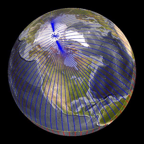
-Earth acts like a giant permanent magnet, producing its own magnetic field.

-Ferromagnetic metals are metals that attract magnets. It appears that all magnets are mad up of these materials. They are: Iron, Nickel, and Cobalt, or mixtures of the three.

DOMAIN THEORY: ALL LARGE MAGNETS ARE MADE UP OF MANY SMALLER AND ROTATABLE MAGNETS, CALLED DIPOLES, WHICH CAN INTERACT WITH OTHER DIPOLES CLOSE BY. IF DIPOLES LINE UP, THEN A SMALL MAGNETIC DOMAIN IS PRODUCED.


OERSTED'S PRINCIPLE: CHARGE MOVING THROUGH A CONDUCTOR PRODUCES A CIRCULAR MAGNETIC FIELD AROUND THE CONDUCTOR.

 -Mapping the magnetic field allows you to predict the direction of the electromagnetic force from the current. Scientists have developed several hand signs to help you predict how magnetic forces act. They are called right hand rules because they involve using your right hand.

RIGHT HAND RULE #1 (RHR#1) FOR CONVENTIONAL CURRENT FLOW:  Grasp the conductor with the thumb of the right hand pointing in the direction of the conventional, or positive, current flow. The curved fingers point in the direction of the magnetic field around the conductor.

-If the wire is coiled, the individual field lines fall on top of each other, thereby strengthening the overall field. Coiling the wire in a linear cylinder also straightens out the field.

RIGHT HAND RULE #2 (RHR#2) FOR CONVENTIONAL CURRENT FLOW: Grasp the coiled conductor with the right hand such that curved fingers point in the direction of conventional, or positive, current flow. The thumb points in the direction of the magnetic field within the coil. Outside the coil, the thumb represents the north (N) end of the electromagnet produced by the coil.

Here are some websites that talk about magnetics:
1.http://www.school-for-champions.com/science/magnetism.htm
2.http://www-spof.gsfc.nasa.gov/Education/Imagnet.html

Also, a very cool and easy to understand video:
Introduction to Magnetism

Tuesday, September 14, 2010

Notes from Page 553-563

Here are my notes for the pages 553-563.

-The amount of current flow in a circuit, and therefore the amount of energy transferred to any useful device depends on two things:
1. The potential difference of the power supply (amount of push)
2. the nature of the pathway through the loads that are using the electric potential energy.

-The more difficult the path, the more opposition there is to a flow.


-The measure of the opposition of flow is called electric resistance.

To measure resistance:

R=V/I

where R is the resistance in volts/ ampere (ohm)
V is the potential difference in volts
I is the resulting current in amperes

-A thinner wire has a larger resistance than a thicker one.


-Ohm found that the V/I ratio was constant for a particular resistor. This law is called the Ohm's Law.

-----------------------------------------------------------------------------------------------------------------------------------------
 Factors that Affect Resistance

-The longer the conductor, the greater the resistance. Factor: Length

-The larger the thickness of the conductor, the less resistance there is. Factor: Cross-sectional area

-Some materials are better conductors than others. Factor: Type of material
-Higher temperatures tend to increase the resistance. Factor: Temperature
------------------------------------------------------------------------------------------------------------------

Kirchhoff's current law: The total amount of current into a junction point of a circuit equals the total current that flows out of that same junction.

Kirchhoff's voltage law: The total of all electrical potential decreases in any complete circuit loop is equal to any potential increases in that circuit loop.

-In any circuit, there is no net gain or loss of energy or electric charge.

Here are some links I found helpful:
1. http://www.the12volt.com/ohm/ohmslaw.asp
2. http://cnx.org/content/m0015/latest/
3. http://physics.about.com/od/electromagnetics/f/KirchhoffRule.htm

Here is a video for Ohm's Law:
http://www.youtube.com/watch?v=_-jX3dezzMg

and one for Kirchhoff's Law:
http://www.youtube.com/watch?v=Mc_g26ixTtA

Monday, September 13, 2010

Ohm's Law Prelab : Chart


 Name
Symbol
Unit
Definition

Voltage

V

Volts (V)
A representation of the electric potential energy per unit charge.

Current

I

Amperes (A)
The total amount of charge moving past a point in a conductor, divided by time taken.

Resistance

R

Ohms (Ω)
A measure of the opposition to current flow.

Power

P

Watts (W)
The rate at which work is done.
 

Sunday, September 12, 2010

Ball Experiment & Series/Parallel Circuits

On Sept 10, our class was presented with a strange "ping pong like" ball as well as an envelope containing 12 questions, each with happy faces on them. According to Mr. Chung, we were to follow the questions and conduct our own mini experiment. The ball had two metal areas and had the ability to light up if certain criteria were met. In the beginning, we had no idea what made the ball light up, but near the end of the experiment, we began to get a rough idea of the physics of the ball. Here are the twelve questions that we had to answer:


1. Can you make the ball work? What do you think makes the ball flash and hum?


Yes, we were able to make the ball work. We think that the ball flashes and hums because it is in fact a circuit, and by touching the ball we somehow activated the circuit by transferring electrons.


2. Why do you have to touch both metal contacts to make the ball work?


Due to the fact that the ball is a circuit, if we were to only use one metal contact the circuit would not be completed. In other words, the current would not continue.

3. Will the ball light up if it touches any other material?

No. We experimented with many materials and we came to the conclusion that not all materials made the ball light up. However, the items that made the ball light up (my binder rings, the bottom of the table) all seemed to be metal based, in other words good conductors. Therefore, we believe that the ball only lights up if it has contact with metal based materials.

4. Which material will make the ball work? Test your hypothesis.

We found out while answering question 3 that metal based materials make the ball work. We tested this out and it indeed work for materials such as the binder rings and the bottom of the table.  

5. This ball does not work for certain individuals. What might cause this to happen?

From our experiment results, we believe that the ball does not work for some individuals due to the fact that they are missing or lacking some material. We think that this element might be iron or copper, or something in that region. I did some further research and found that the lack of iron in the blood can lead to an illness called iron-deficiency anemia, a disorder that is actually quite common. Perhaps people who suffer from this disorder would not be able to make the ball work.

6. Can you make the ball work with the 5-6 members in your group? Will it work with the entire class?

Yes, it will work, as long as the members all have physical contact with each other.


7. What kinds of circuits can you make with one energy ball?

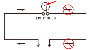
We were able to make two types of circuits: simple and opened. To make the simple circuit, we just connected with everyone in the group. To create the opened circuit, one person simply lost contact with the group and therefore the ball failed to light up.

Diagram of an open circuit

8. Given two balls (two groups): Can you make both energy balls light up?

Yes, it was actually easier than we thought. We basically created a larger simple circuit; the general idea was the same. Everyone held each others pinkies and we made both balls light up.


9. What do you think would happen if one person in the group let go?

We think that the ball would fail to light up because the connection would be lost. The simple circuit would turn into an opened circuit.


10. Does it matter who lets go?

No, it doesn't matter because everyone is part of the connection. No matter who let's go, the connection will be lost.

11. Can you create a circuit where only one ball lights up?

Yes-we had to create a parallel circuit where one person had to let go. One ball lit up while the other ball failed.

12. What is the minimum number of people required to do this?

We determined that minimum number of people required to do this successfully would probably be four.

--------------------------------------------------------------------------------------------------------------------------------------

What is the difference between a series circuit and a parallel circuit?

In a series circuit, the loads are connected one after another using only one path. In a parallel circuit, the loads are placed side by side. Both arrangements alter the way current act in parts of the circuit. The potential difference is also affected. In a series circuit, every device must be working properly in order for the circuit to work. If one device fails, the whole system will fail. In a parallel circuit, each device uses its own circuit and therefore if one device fails, the other devices should continue working properly.


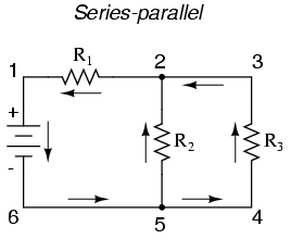
You can also connect the two types of circuits and create a series-parallel circuit.


Here are some links regarding series and parallel circuits:

1.http://www.allaboutcircuits.com/vol_1/chpt_5/1.html
2.http://www.ndt-ed.org/EducationResources/HighSchool/Electricity/seriesparallelcircuits.htm

Here is a video that I found quite helpful:
http://www.youtube.com/watch?v=E8AZBR8Zz04

Thursday, September 9, 2010

Tall Structure Questions

1. Physics of tall structures.

In the past, tall structures have always been thought of as rewarding but extremely hard to build and maintain projects. It makes sense: a taller structure that has the same shape as a shorter, more compact structure will obviously be less stable. Despite this, building tall structures is not as difficult as some people think, as long as a few rules are met. During our experiment, my group's structure failed to meet a few of the criteria and therefore it tumbled to a sad fate. If we changed a few things, the outcome could have been very different.

2. What makes a tall structure stable?

There are a few characteristics that make certain tall structures stable.

1. The structure must have a strong base that makes up much of the weight.

2. The top of the structure must be lighter and not as wide as the bottom of the structure.

3. The structure should have a low centre of gravity.

4. The structure must be made of high quality material.

5. The screws and other devices used must be locked securely in place. 

6. It is preferred if triangles are used because they are the strongest shapes.

7. There must be some symmetry; if not, the building must be heavier on one side than the other.


3. What is the centre of gravity?

The centre of gravity is the average location of the total mass of a structure. Another term that is often used is the barycenter.